Block model XYZ to IJK conversion
Introduction
A block model consists of a three-dimensional grid of blocks, defined relative to a set of axes , , and that represent "real world" directions aligned with a coordinate system such as WGS84. The position of each block within the model is defined by its centroid, which is an XYZ location in space indicating the centrepoint of the block. In this document, locations are denoted using round brackets, e.g. (2, 3, 4). A number of factors make working with these centroid locations inefficient.
- In general, centroid location values are not integers. Block size values themselves are not necessarily integers; the model origin may have a non-integer offset; and if neither of these is the case, a block size that is an odd integer would still result in fractional centroid locations.
- Block models are often not aligned with the , , and axes. Surveys may have been taken in a direction that is not north-south or east-west aligned, or boreholes may not have been taken vertically. This results in a block grid where the centroids of neighbouring blocks are not separated by a simple increment on one axis.
BMS deals with this complexity by internally transforming the block centroids into integer block indices, generally referred to as 'IJK indices', aligned with the model. It converts these back to XYZ centroids when outputting block models in response to queries.
Definition of IJK indices
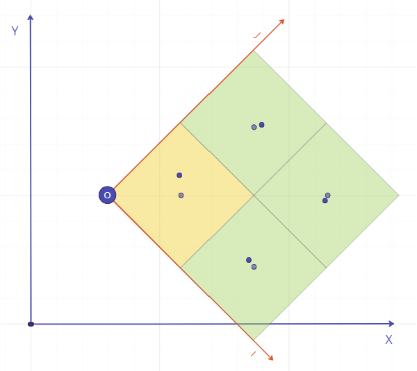
BMS internally transforms the block model to use model-aligned axes , , and . A block's 'IJK index' consists of three integers, representing the block's index within the three-dimensional grid of blocks on these axes. In this document, indices are denoted using square brackets, e.g. [1,2,3]. Index values are 0-based, meaning that the block with an IJK index of [0,0,0] represents the block that is at the "corner" of the block model. Its neighbors in each direction would have the IJK indices [1, 0, 0], [0, 1, 0], and [0, 0, 1].
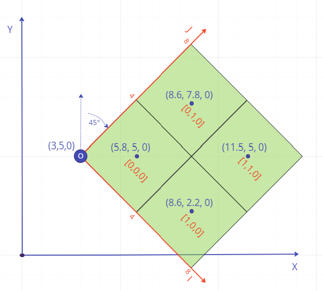
Above: A 2x2x1 model rotated 45° around the axis. The origin is at (3, 5, 0) and block size is 4x4x1; blocks are marked with the (x, y, z) locations of the centroids, and the [i, j, k] block indices.
Using model-aligned integer indices has advantages for data validation, efficiency of storage, and query and reporting performance.
Block models include in their definition either n_blocks (for a regular model) or n_parent_blocks (for a sub-blocked model). This defines the size of the block model in blocks, on each axis.
"n_blocks": {
    "nx": 1000,
    "ny": 500,
    "nz": 200
}
More properly, nx refers to the range of blocks (or parent blocks if sub-blocked) available on the axis, ny for the axis, and nz for the axis; a block's index must be in the range .
Block model origins & rotations
The transformation of the model centroids from XYZ ("real world") to IJK (model-aligned) values is defined by two parts of the block model configuration: origin and rotation.
Origin
The property model_origin represents the offset of the model relative to the XYZ origin.
"model_origin": {
    "x": 200,
    "y": 100,
    "z": 0
},
Rotation
The property block_rotation defines the rotation of the block model. This is a list of clockwise rotations around given axes:
"block_rotation": [
    {
        "angle": 60,
        "axis": "x"
    },
    {
        "angle": -50,
        "axis": "y"
    }
],
The rotations are applied as matrices. The combined equation for the rotation is given by:
where is the location in the IJK space, is the location in XYZ space, and is the rotation matrix for the ith rotation. Two rotations around the same axis cannot be consecutive items within the list of rotations.
The rotation matrix used for each rotation is equivalent to the following, depending on the selected axis:
Model update: XYZ centroids to IJK indices
When files are processed as part of the creation of a new version of a model, the blocks are transformed from using XYZ-based centroids, to using IJK-based indices. The following process is followed:
- The block centroids are translated to be relative to the model origin, by subtracting
model_originfrom each. - The blocks are rotated from XYZ space to IJK space. As the rotations in
block_rotationdefine the rotation from IJK to XYZ, the transpose of the combined rotations is used. - The IJK index for each block is calculated from the transformed centroid, based on the block size, from either
block_size(for a regular model) orparent_block_size(for a sub-blocked model):
"block_size": {
    "x": 3,
    "y": 2,
    "z": 1
},
The index on each axis is calculated by performing an integer div; so for the axis, where is the i index, the transformed x position of the centroid, and the block size in the x direction:
Index values of less than 0 or greater than 4,294,967,295 (uint32.max) are considered errors, and will result in the update job failing. See the Error File section below for more detail on how this is reported. Note, the index values are not validated against n_blocks, and can be outside this range; the system will calculate the actual bounding box for the blocks in the uploaded file, and automatically attach that to the block model version.
Epsilon values and centroid validation
The "epsilon" ε for a block is the vector distance between its transformed centroid in IJK space, and the expected location of the centroid for that IJK index. This is calculated for each axis using a mod operation; so for i, where is the ε distance on the axis, the transformed x position of the centroid, and the block size in the x direction:
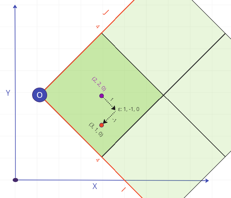
Above: Example of an invalid centroid, with an expected centroid in IJK space of (2, 2, 0), but an actual at (3, 1, 0). The epsilon ε, also in IJK space, is (1, -1, 0).
The epsilon distance vector is used to verify the correctness of the transformed data. If the size of any component of epsilon exceeds 10% of the block size on that axis, the block is considered to be invalid, and will result in the update job failing. See the Errors and the error file section below for more detail on how this is reported. There are several possible reasons why this might occur; note that multiple of these could apply at the same time.
Incorrect model rotation(s)
A block model uploaded with an incorrect rotation is likely to result in at least some blocks' epsilon values exceeding the 10% tolerance. A very small error in the rotation may mean that blocks near the origin pass, while blocks further away fail; any larger error would result in most or all blocks failing.

Above: Example of a 5° error in rotation, and the resulting difference between expected and actual centroids. The epsilon for [0,0,0] is small enough to pass, but the others exceed 10% and would result in the blocks failing.
Incorrect model origin
A block model uploaded with an incorrect origin may result in blocks failing, if the error in origin location exceeds 10% of the block size. In this case, the failure is likely to be binary; either all blocks fail by the same amount, or none fail (if the error is close to a multiple of the block size).
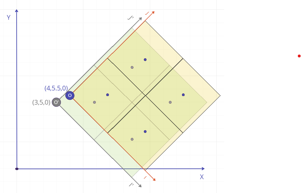
Above: Example of an error in origin location, and the resulting difference between expected and actual centroids. Each centroid is out by the same epsilon (equal to the error in the origin, in IJK space), resulting in all blocks failing.
Incorrect block size
An error in the block size definition is likely to result in at least some blocks' epsilon values exceeding the 10% tolerance. A very small error in the block size may mean that blocks near the origin pass, while blocks further away fail; any larger error would result in most or all blocks failing, unless the correct block size was an exact multiple of that given (which would result in a "gappy" block model where every Nth index value would be used).
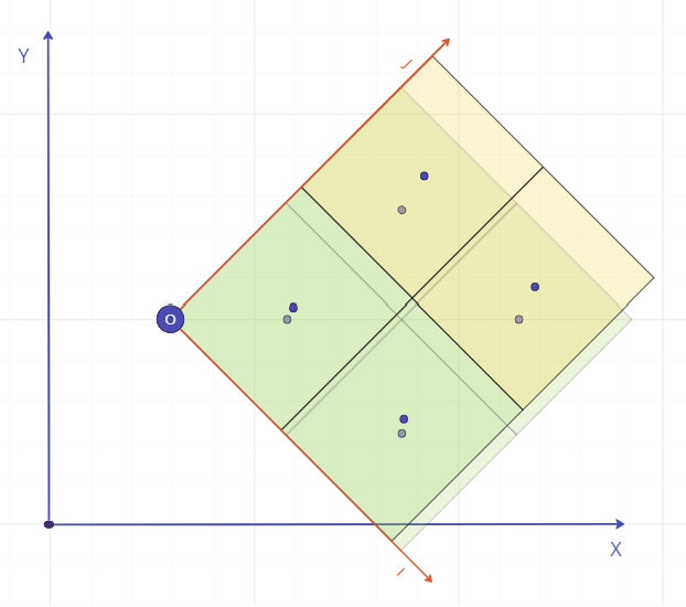
Above: Example of an error in block size. The expected size is 4x4x1; the actual centroids are on 3.75x4.5x1. The epsilon for each block is equal to its index x the block size error in each dimension; blocks near the origin pass, while those further away fail.
Inaccurate centroid location
An individual centroid position in the uploaded file that is simply too far from the expected centre of the block will also result in the block failing. This may be due to misconfiguration in the source application, or invalid source data.
Above: Example of variation in centroid accuracy. Most of the centroids are close to the expected location, but one is outside the 10% tolerance. This will result in that one block failing, with no systemic pattern.
Sub-blocks
For sub-blocking model types, sub-blocks are transformed from XYZ space to IJK space along with the parent blocks, and a separate sub-process is followed to calculate the appropriate sub-block indices for each sub-block. For details of this process for the different sub-blocking types, see the sub-blocking guide.
Sub-block sizes are also validated by comparing their dx, dy, and dz sizes with the expected block size for the relevant level of sub-block. A tolerance of 10% is allowed on the expected sub-block size for each axis, except for flexible models where the tolerance is 10% of the cell size of the sub-block grid.
Sub-block epsilons are calculated and validated in an equivalent manner to parent blocks: again, a tolerance of 10% of the sub-block size is allowed for deviation from the expected sub-block centroid, except for flexible models where the tolerance is 10% of the cell size of the sub-block grid.
Errors and the error file
When an error occurs in processing a block model version upload, the upload job will be marked having a job_status of FAILED, and the job payload will be set to the standard error response data structure, indicating the type and details of the error. If the error relates to one or more specific blocks in the model, such as the index or centroid being out of bounds, the job payload will have the download_url property set to point at the error file.
The error file is itself a block model in Parquet format, that contains a row for each block that contains errors. The columns included depend on the model type; all columns are of type Double, and are set to NaN if the condition is not met.
Regular
| Column name | Description | Condition |
|---|---|---|
| ex | Centroid x position | All |
| ey | Centroid y position | All |
| ez | Centroid z position | All |
| epsx | Epsilon in the direction | Epsilon error on block |
| epsy | Epsilon in the direction | Epsilon error on block |
| epsz | Epsilon in the direction | Epsilon error on block |
| ei | Index in the direction | Index error on block |
| ej | Index in the direction | Index error on block |
| ek | Index in the direction | Index error on block |
Sub-blocked, except for flexible models
| Column name | Description | Condition |
|---|---|---|
| ex | Centroid x position | All |
| ey | Centroid y position | All |
| ez | Centroid z position | All |
| edx | Block size in the direction | Block size error |
| edy | Block size in the direction | Block size error |
| edz | Block size in the direction | Block size error |
| epsx | Epsilon in the direction | Epsilon error on block |
| epsy | Epsilon in the direction | Epsilon error on block |
| epsz | Epsilon in the direction | Epsilon error on block |
| ei | Index in the direction | Index error on block |
| ej | Index in the direction | Index error on block |
| ek | Index in the direction | Index error on block |
Note that if a block size error is recorded for a block, the other error columns will be unset as with an inaccurate block size, epsilons and indexes cannot be calculated.
Flexible models
| Column name | Description | Condition |
|---|---|---|
| ex | Centroid x position | All |
| ey | Centroid y position | All |
| ez | Centroid z position | All |
| edx | Block size in the direction | Block size error |
| edy | Block size in the direction | Block size error |
| edz | Block size in the direction | Block size error |
| epsx | Epsilon in the direction | Epsilon error on block |
| epsy | Epsilon in the direction | Epsilon error on block |
| epsz | Epsilon in the direction | Epsilon error on block |
| ei | Index in the direction | Index error on block |
| ej | Index in the direction | Index error on block |
| ek | Index in the direction | Index error on block |
| estart_si | Start sub-block index in the direction | Sub-block index error |
| estart_sj | Start sub-block index in the direction | Sub-block index error |
| estart_sk | Start sub-block index in the direction | Sub-block index error |
| eend_si | End sub-block index in the direction | Sub-block index error |
| eend_sj | End sub-block index in the direction | Sub-block index error |
| eend_sk | End sub-block index in the direction | Sub-block index error |
Note that if a block size error is recorded for a block, the other error columns will be unset as with an inaccurate block size, epsilons and indexes cannot be calculated.
Query: IJK indices to XYZ centroids
BMS does not store the raw centroids, only the IJK indices. When producing an output block model in response to a query, BMS performs the reverse process to regenerate XYZ centroids for each block. The process for a regular block model is as follows:
- Calculate centroid locations on the , , and axes from IJK indices, based on the model's block size
- Rotate the centroids back to relative to the XYZ axes, using
block_rotation: , where is the IJK location and is the XYZ location - Translate the centroids to their correct location by adding
model_originto each, to produce the centroid location columnsx,y, andzin the output file.
For sub-blocked models, BMS also uses additional sub-block index columns when calculating the centroid location for a sub-block. It also uses the sub-block index columns to regenerate the sub-block size columns dx, dy, and dz in the output file.
Note that as the output centroid and size values are generated from index data, they are precise values for the block model configuration, and are not based directly on the source block data.
XYZ bounding boxes and rotations
Bounding boxes are used in update, query, and delta operations to define the volume of the model being referenced. They can be defined either based on numerical position ranges on the , , and axes, or index ranges in IJK space.
{
    "i_minmax": {
        "min": 10,
        "max": 90
    },
    "j_minmax": {
        "min": 10,
        "max": 90
    },
    "k_minmax": {
        "min": 0,
        "max": 9
    }
}
{
    "x_minmax": {
        "min": 0.5,
        "max": 9.5
    },
    "y_minmax": {
        "min": 2.0,
        "max": 10.0
    },
    "z_minmax": {
        "min": 0,
        "max": 10
    }
}
When processed, bounding boxes are always applied aligned with the block model: while an XYZ-based bounding box is defined by ranges on the , , and axes, these are treated as two locations (minimum-corner and maximum-corner) defining opposite corners of the bounding box, which are then translated using the model origin and rotated using the model rotations in the same manner as XYZ centroids are transformed on upload.
These translated corners are then used to define minimum and maximum ranges of the bounding box on the , , and axes. The faces of the bounding box are parallel to the axes. Due to this transformation, the values used for minimum and maximum in XYZ should be those that correspond to the minimum and maximum corners in IJK space, so as to be transformed to the correct minimum and maximum. In some cases this may require an input range for an axis to have the minimum greater than the maximum!
Blocks are considered to be inside an XYZ bounding box if their centroid lies within the defined volume. For IJK index bounding boxes, the index ranges are inclusive.
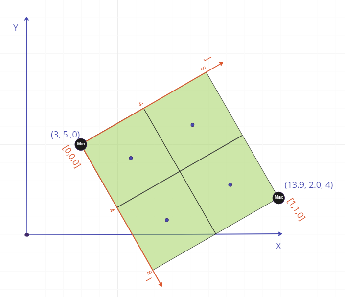
Above: A bounding box on a block model rotated 60° around the axis.
In the above example of a 60° rotated block model with a block size of 4x4x4, we have a bounding box which in IJK index terms would be:
{
    "i_minmax": {
        "min": 0,
        "max": 1
    },
    "j_minmax": {
        "min": 0,
        "max": 1
    },
    "k_minmax": {
        "min": 0,
        "max": 0
    }
}
The equivalent XYZ bounding box is based on the XYZ coordinates of the minimum and maximum corners in IJK space, and so are the following:
{
    "x_minmax": {
        "min": 3,
        "max": 13.9
    },
    "y_minmax": {
        "min": 5,
        "max": 2
    },
    "z_minmax": {
        "min": 0,
        "max": 4
    }
}
Note that for the y axis, min is greater than max.